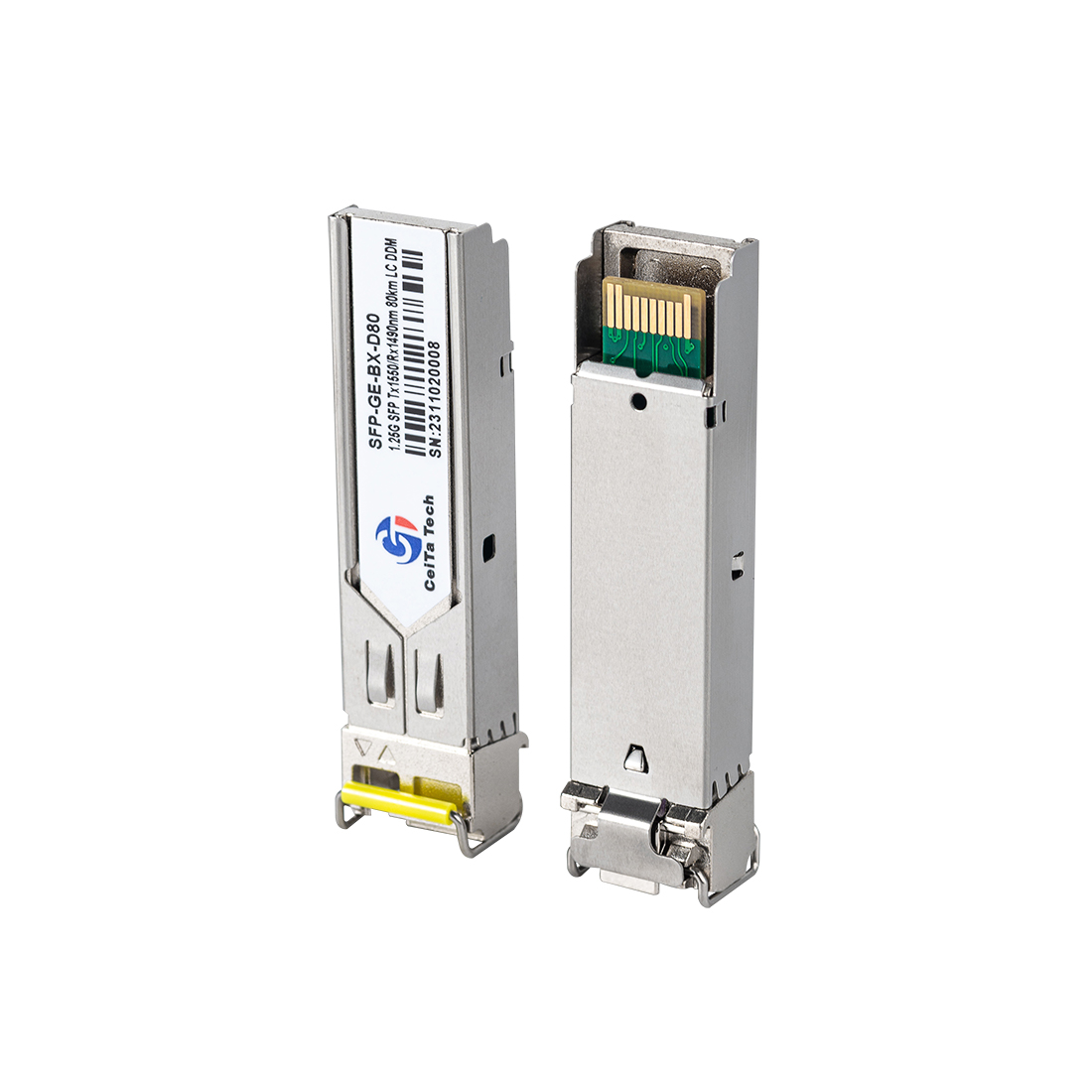
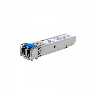
1.25Gbps 1490/1550nm 80/100/120km LC/SC DDM BIDI SFP Module

Standard
◉ Compliant with SFP MSA (INF-8074i)
◉ Compliant with SFF-8472
◉ Compliant with IEEE 802.3z
Technical Indicators
|
Absolute Maximum Ratings |
|||||||||||||||||
|
Parameter |
Symbol |
Min |
Max |
Unit |
|||||||||||||
|
Storage temperature |
TS |
-40 |
85 |
°C |
|||||||||||||
|
Power Supply Voltage |
Vcc |
0 |
3.6 |
V |
|||||||||||||
|
Relative Humidity |
RH |
5 |
95 |
% |
|||||||||||||
|
Recommended Operating Conditions |
|||||||||||||||||
|
Parameter |
Symbol |
Min |
Typical |
Max |
Unit |
Notes |
|||||||||||
|
Operating Case Temperature |
TC |
-5 |
|
70 |
°C |
CT-B45(54)12-80DC |
|||||||||||
|
Power Supply Voltage |
Vcc |
3.13 |
3.3 |
3.47 |
V |
|
|||||||||||
|
Data Rate |
|
|
1.25 |
|
Gbps |
|
|||||||||||
|
Fiber Length 9/125μm core SMF |
|
|
|
80 |
km |
|
|||||||||||
|
Electrical Characteristics |
|||||||||||||||||
|
Parameter |
Symbol |
Min |
Typical |
Max |
Unit |
Notes |
|||||||||||
|
Total Supply Current |
Icc |
|
|
300 |
mA |
|
|||||||||||
|
Transmitter |
|||||||||||||||||
|
Transmitter Differential Input Voltage |
|
400 |
|
2400 |
mV |
|
|||||||||||
|
Tx_Fault Output Voltage - High |
VOH |
2.4 |
|
Vcc |
V |
LVTTL |
|||||||||||
|
Tx_Fault Output Voltage - Low |
VOL |
0 |
|
0.4 |
V |
LVTTL |
|||||||||||
|
Tx_Disable Input Voltage - High |
VIH |
2 |
|
Vcc |
V |
LVTTL |
|||||||||||
|
Tx_Disable Input Voltage - Low |
VIL |
0 |
|
0.8 |
V |
LVTTL |
|||||||||||
|
Input Differential Impedance |
ZIN |
85 |
100 |
115 |
Ω |
|
|||||||||||
|
Receiver |
|||||||||||||||||
|
Electrical Characteristics |
|||||||||||||||||
|
Parameter |
Symbol |
Min |
Typical |
Max |
Unit |
Notes |
|||||||||||
|
Receiver Differential Output Voltage |
|
600 |
|
1600 |
mV |
|
|||||||||||
|
LOS Output Voltage - High |
VOH |
2.4 |
|
Vcc |
V |
LVTTL |
|||||||||||
|
LOS Output Voltage - Low |
VOL |
0 |
|
0.4 |
V |
LVTTL |
|||||||||||
|
Output Differential Impedance |
ZOUT |
90 |
100 |
110 |
Ω |
|
|||||||||||
|
Optical Transmitter Characteristics |
|||||||||||||||||
|
Parameter |
Symbol |
Min |
Typical |
Max |
Unit |
Notes |
|||||||||||
|
Average Output Power |
POUT |
0 |
2 |
5 |
dBm |
|
|||||||||||
|
Center Wavelength |
λC |
1470 |
1490 |
1510 |
nm |
CT-B4512-80DC |
|||||||||||
|
|
|
1530 |
1550 |
1570 |
|
CT-B5412-80DC |
|||||||||||
|
Spectrum Width(-20dB) |
Δλ |
|
|
1 |
nm |
|
|||||||||||
|
Side Mode Suppression Ratio |
SMSR |
30 |
|
|
dB |
|
|||||||||||
|
Extinction Ratio |
ER |
9 |
|
|
dB |
|
|||||||||||
|
Transmitter OFF Power |
POFF |
|
|
-45 |
dBm |
|
|||||||||||
|
Jitter P-P |
TJ |
|
|
0.1 |
UI |
|
|||||||||||
|
Output Eye Diagram |
Complies with IEEE802.3z |
||||||||||||||||
|
Optical Receiver Characteristics |
|||||||||||||||||
|
Parameter |
Symbol |
Min |
Typical |
Max |
Unit |
Notes |
|||||||||||
|
Center Wavelength |
λC |
1530 |
1550 |
1570 |
nm |
CT-B4512-80DC |
|||||||||||
|
|
|
1470 |
1490 |
1510 |
|
CT-B5412-80DC |
|||||||||||
|
Receiver Sensitivity |
PSEN |
|
|
-26 |
dBm |
Note 1 |
|||||||||||
|
Input Saturation Power (Overload) |
PSAT |
-3 |
|
|
dBm |
|
|||||||||||
|
LOS De-assert Level |
LOSD |
|
|
-27 |
dBm |
|
|||||||||||
|
LOS Assert Level |
LOSA |
-40 |
|
|
dBm |
|
|||||||||||
|
LOS hysteresis |
HYS |
0.5 |
|
6 |
dB |
||||||||||||
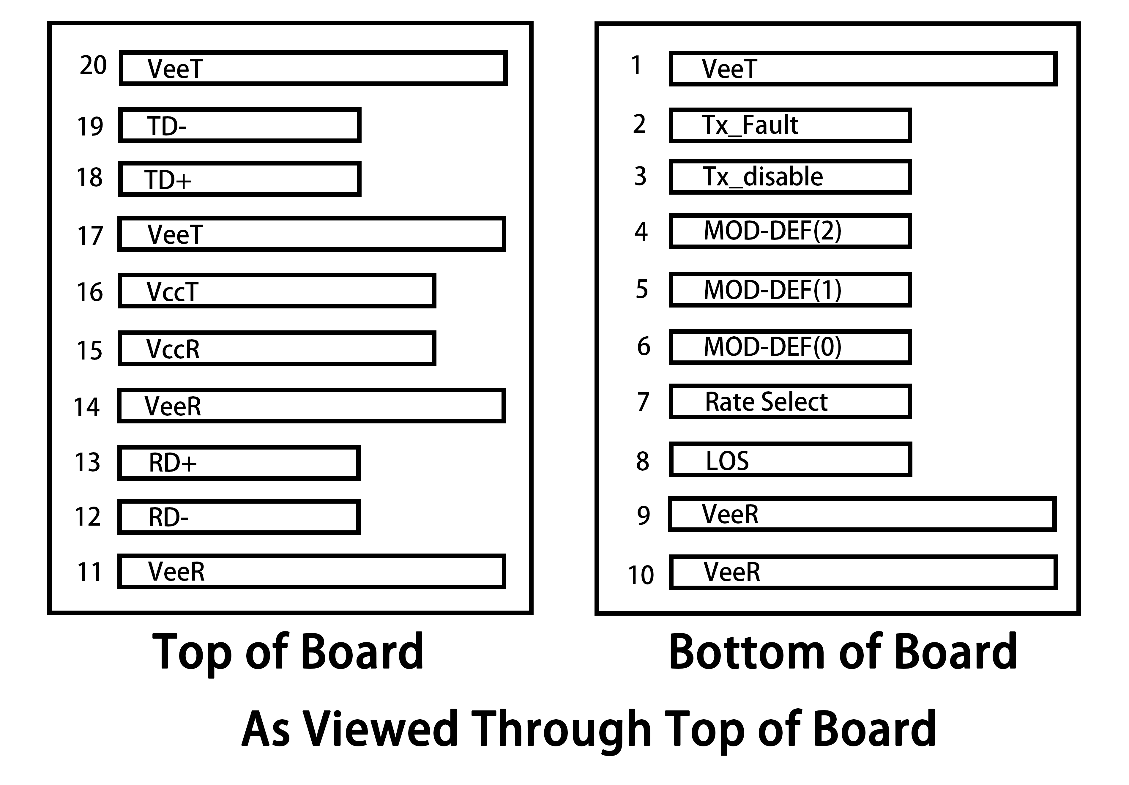
Pin Definition
|
Pin No |
Symbol |
Name/Description |
Power Seq. |
Notes |
|
1 |
VeeT |
Transmitter Ground |
1st |
|
|
2 |
TX Fault |
Transmitter Fault Indication, Logic 1 indicates Transmitter Fault. |
3rd |
1 |
|
3 |
TX Disable |
Transmitter Disable, Transmitter disables on high or open. |
3rd |
2 |
|
4 |
MOD-DEF(2) |
Module Definition 2. Data line for two wire Serial ID. |
3rd |
3 |
|
5 |
MOD-DEF(1) |
Module Definition 1. Clock line for two wire Serial ID. |
3rd |
3 |
|
6 |
MOD-DEF(0) |
Module Definition 0. Grounded within the module. |
3rd |
3 |
|
7 |
Rate Select |
Not Connected |
3rd |
|
|
8 |
LOS |
Loss of Signal indication. Logic 1 indicates Loss of Signal. |
3rd |
4 |
|
9 |
VeeR |
Receiver Ground |
1st |
|
|
10 |
VeeR |
Receiver Ground |
1st |
|
|
11 |
VeeR |
Receiver Ground |
1st |
|
|
12 |
RD- |
Inverse Received Data Out, AC coupled |
3rd |
|
|
13 |
RD+ |
Received Data Out, AC coupled |
3rd |
|
|
14 |
VeeR |
Receiver Ground |
1st |
|
|
15 |
VccR |
Receiver Power |
2nd |
|
|
16 |
VccT |
Transmitter Power |
2nd |
|
|
17 |
VeeT |
Transmitter Ground |
1st |
|
|
18 |
TD+ |
Transmit Data In, AC coupled |
3rd |
|
|
19 |
TD- |
Inverse Transmit Data In, AC coupled |
3rd |
|
|
20 |
VeeT |
Transmitter Ground |
1st |
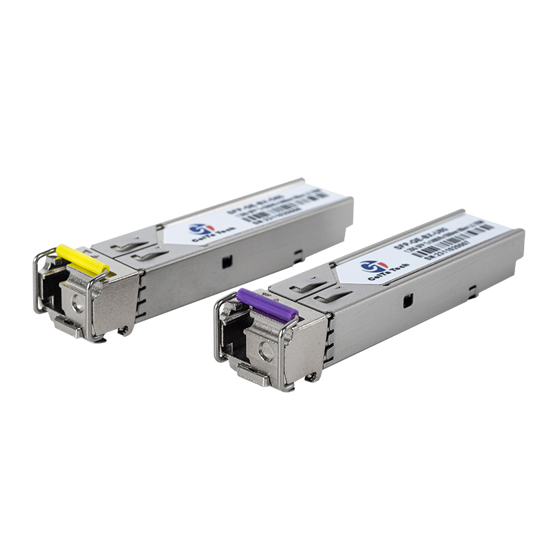
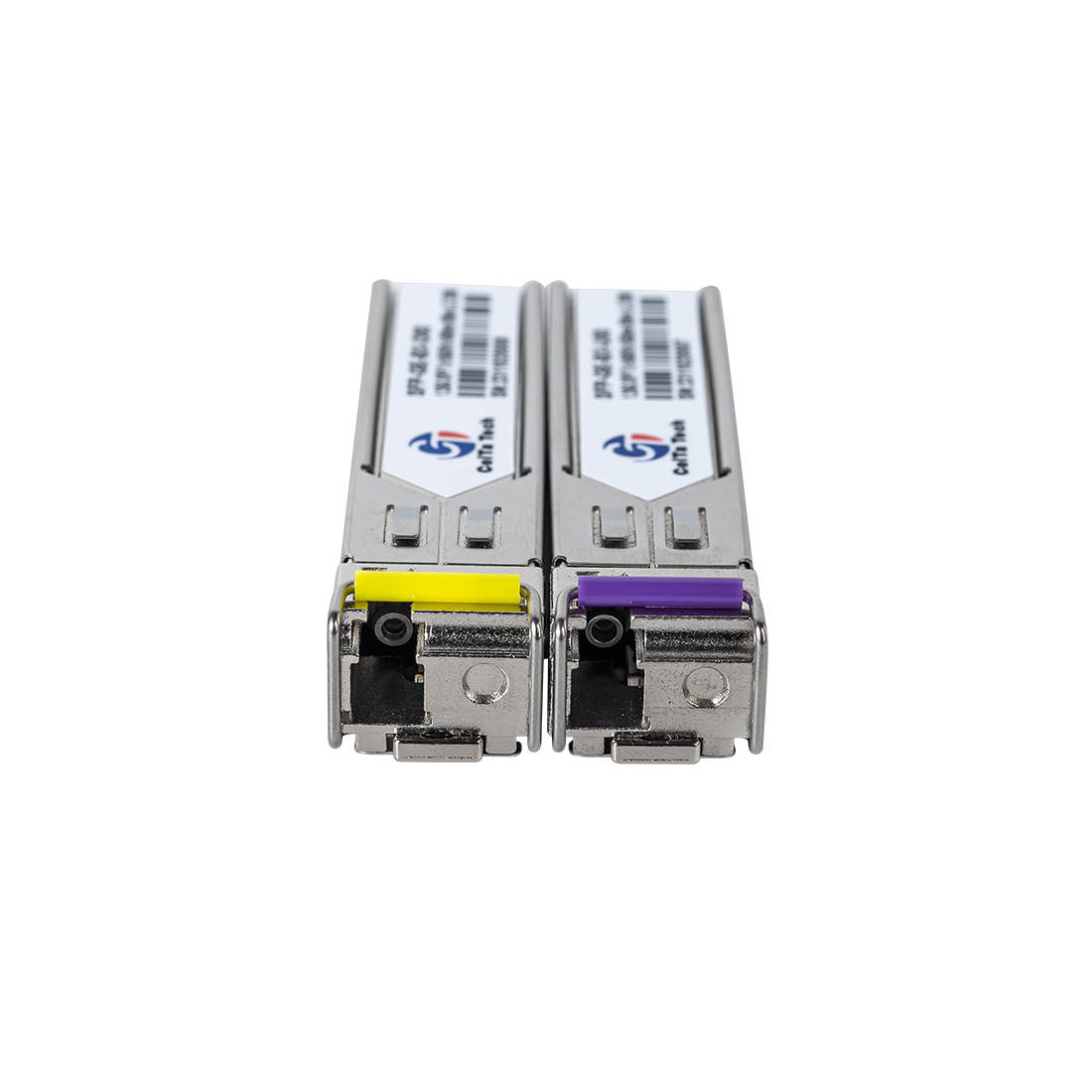
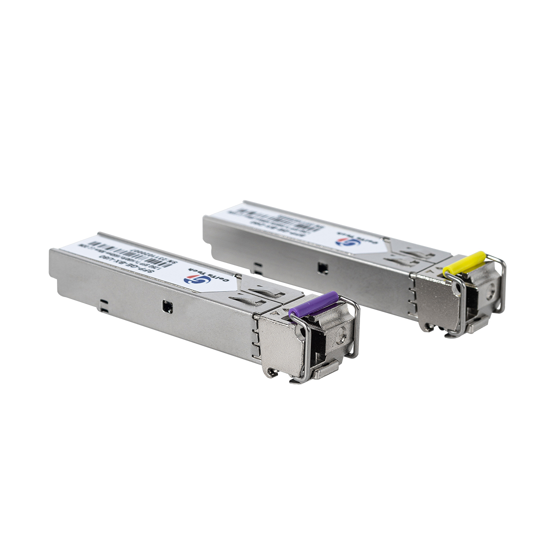
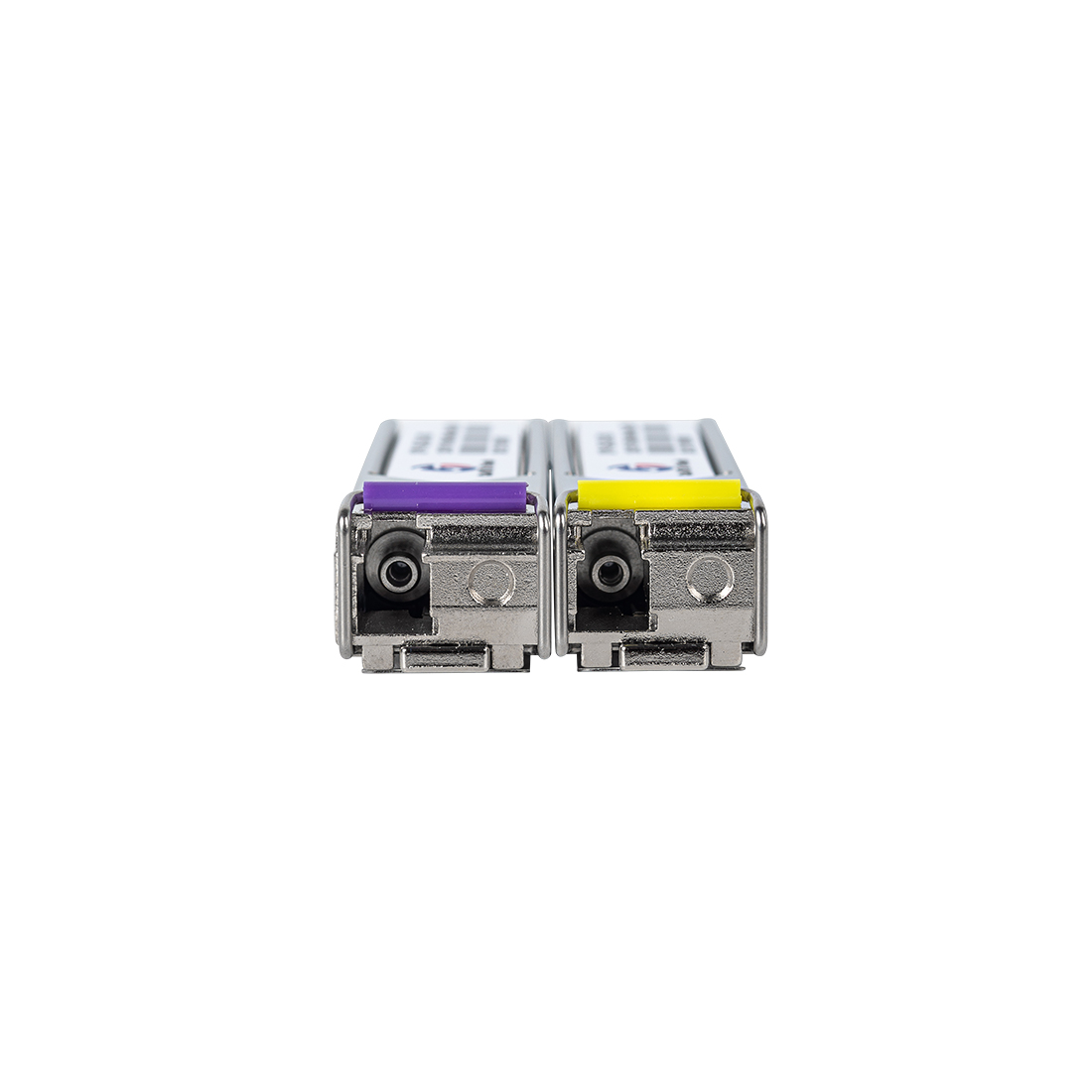
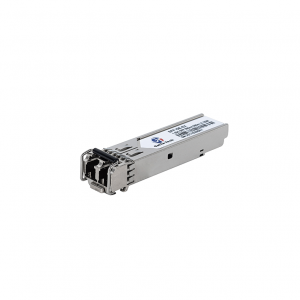
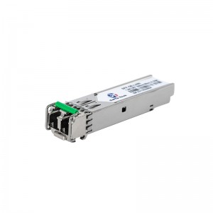
Product Picture

1-300x300.png)
-300x300.jpg)